Formal drawings
Formal drawings are a more precise style of drawing. They can be produced by hand or with computer aided design (CAD) packages.
Formal hand drawings use tools such as rulers and set squares to ensure accuracy and neatness.
Using computer aided design (CAD) allows the user to quickly make changes, and the drawings can be digitally shared and copied with ease.
Formal drawings are used when showing an idea to a client, showing measurements or getting feedback from a user group.
Formal drawing of a toy car
| Description | Materials | Part | Length | Height | Quantity |
|---|---|---|---|---|---|
| Top lid | Acrylic | 1 | 220mm | 200mm | 1 |
| Left side | Plywood | 4 | 321mm | 210mm | 2 |
| Front window | Acrylic | 6 | 200mm | 90mm | 1 |
| Front top | Plywood | 2 | 200mm | 101mm | 1 |
| Front | Plywood | 3 | 200mm | 120mm | 1 |
| Wheel | Plywood | 5 | 70mm | - | 4 |
| Back | Plywood | - | 200mm | 210mm | 1 |
Working drawings
Design and development involves creating working drawings and parts lists to enable a third party to manufacture the design. Working drawings are sent from a designer to a manufacturer to enable them to build a product.
Exploded diagrams
Exploded diagrams show how a product can be assembled and how the separate parts fit together, with dotted lines showing where the parts slide into place. The diagrams also show components that would usually be hidden in a solid drawing.
Exploded diagrams can take the place of detailed written instructions, meaning they can explain the construction of something without the barrier of different languages. They are widely used as instructions for self-assembly furniture.
Elevations
Elevations are the sides of an item you can see on the drawing, e.g. front elevation or side elevation. The top is referred to as the ‘plan’. These drawings enable detailed measurements to be added for every section of the product.
This isometric drawing shows the plan and front and side elevations of the shape.
- Horizontal lines should be drawn at a 30° angle
- Vertical edges should be drawn as vertical lines
- Parallel edges drawn as parallel lines
You can find more information about isometric drawings in sketching and modelling
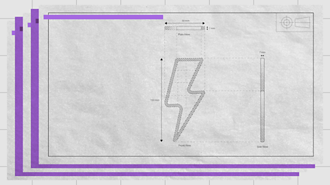
Orthographic projections
Orthographic projections are working drawings in either a first or third angle projection and show each side of a design. They are used to show an object from every angle to help manufacturers plan production.
Starting with a front view of a product, construction lines show where areas join and are used to draw a side and plan (top) view, ensuring that the drawing is accurate from all angles. These drawings are to scale and must show dimensions.
Third angle projections
Third angle projection is an accurate method to produce ‘working drawings’. The position of the plan, front and side views are important in this method of drawing.
In third-angle projection, the view of a component is drawn next to where the view was taken.
What you see from the right would be drawn on the right and what you see from looking at the top will be drawn above.
First Angle Projections
In first-angle projection, the view is drawn on the other end of the component, at the opposite end from where the view was taken.
Standard lines
Orthographic projections have a set of standard lines to show different aspects of the diagram. These lines allow complex shapes to be drawn simply in 2D.
Computer aided design (CAD)
Computer aided design (CAD) is the use of computer software to design new products in both in 2D and 3D. Some of the software commonly used in schools is 2D TechSoft and SolidWorks for 3D designs
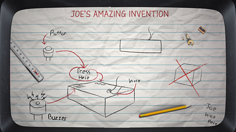
ANIMATION SEQUENCE
JOE
Hello and welcome back to another stimulating episode of Tech Bitez.Today we are exploring the world of CAD, which stands for Computer Aided Design. Now, we had a few issues with our sketches, so I thought this would be the perfect opportunity to give CAD a go. It's computer aided, so how hard could it be?
SANDY
Hard. It's hard. Really useful, but tricky to get the hang of.
JOE
Maybe for you, but I grew up with computers, so I think I'll be able to handle it.
SANDY
Fine. But don't come crying to me when you've been at it for 5 hours and still haven't worked out how to extrude your first piece.
JOE
I’ll be fine. Just you wait and see.Hey Google, what does extrude mean?
ANIMATION SEQUENCE
SANDY
Okay, Joe, maybe I'll just help a little bit with this one.
Your first step should be to sketch out the general shape of your design.
Everything in the CAD program is defined in space. You will therefore be required to choose which plane you want to work on.For this project, we will choose the top plane.When beginning your sketch, it is also helpful to start from the origin point at the centre of the screen.Once you have your general shape, you will need to define it. This will ensure that the sketch is drawn to the correct size. You can do this using smart dimensions.Selecting each line allows you to enter the exact value you require. Once this has been done for each edge, the outlines of the shape will turn black. This shows it has been fully defined and is ready to extrude. To turn our flat 2D shape into a 3D model, you will need to extrude it. In the features tab, select the extrude boss based option. Then define how much you want to extrude your shape. We now have a 3D shape.
Our next step should be creating the studs on the top of the model.Simply sketch out the general shapes of the studs. You can use smart dimensions to resize the shapes and define where they are placed. This will allow you to make sure they are all a uniform size and distance from the edge. Once you are happy that everything is in place, you are ready to extrude the studs. Now we have our 3D design.
Our next step is to hollow it out. This can be done using the shell function. You just need to select the face you would like to shell from and input the value for how thick you would like the edges.
Our last step for the design is to smooth out some of the edges. This can be achieved using the fillet feature. You simply select the fillet tool and then select the edges you would like to fillet.Enter the value for how much you would like to fillet. The program will give you a preview to visualise this before confirming.
And there you have it, your finished model.
JOE
See, I told you I could do it.
CAD software allows you to easily visualise what a product is going to look like when it is made. The designs made on this software can be easily transferred to machines such as a laser cutter of 3D printer. This is known as Computer aided manufacture (CAM).
| Advantages of CAD | Disadvantages of CAD |
|---|---|
| Ideas can be drawn and developed quickly | Expensive to set up |
| Designs can be viewed from all angles and with a range of materials | Needs a skilled workforce |
| Some testing and consumer feedback can be done before costly production takes place | Difficult to keep up with constantly changing and improving technology |
| It becomes easier to design and test a range of ideas | Computers can fail |
Test yourself
More on Design and communication
Find out more by working through a topic
- count1 of 4
- count2 of 4

- count3 of 4